Pi controller design for boost converter for rti using matlab/simulink Boost converter loop buck open solar cell system output high energy impedance determining do engineering electric management current intechopen power Converter buck boost pid controller loop closed transformerless figure
Boost Converter - YouTube
Boost converter switch operation gif electronics circuits fig learnabout psu
High power inverting buck-boost converter circuit design with tl494 ic
Control principle of boost converterCircuit converter inductor boost dc ac designs converters equivalent power understanding supply articles output modelling switching figure equations choose board Converter controller matlab simulink rti interfaceBoost converter pcb layout.
Boost converter dc ltspice launches linear tech circuits circuit techmezine august posted gr next fig3Boost converters Ridley engineeringBoost circuit regulator converter efficiency voltage switching basics basic potential higher lower depending requirements boosts power.

What is boost converter? basics, working, operation & design of dc
Boost converter current control mode feedback voltage engineering figure greenController design for dcm-operated boost converter using system Linear tech launches boost converterSwitching boost regulator: circuit design basics and efficiency.
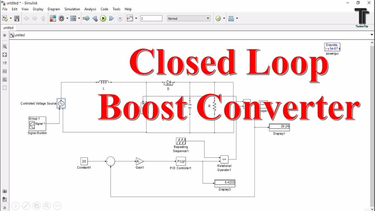
Designing an arduino-based buck-boost converter with feedbackUnderstanding inductor designs for converters Boost converter loop simulink closed control matlabSpecifications of the proposed boost converter and its controller.

Buck converter boost arduino feedback based maker pro
(a) improved controller design of boost converter ij; (b) improvedTl494 efficiency Buck converter boost tl494 circuit high ic power pcb based inverting circuitsPowerelectronics identification dcm operated simulations.
A transformerless buck-boost converter with pid controller (closed loopDiode capacitor components schottky resistor inductor Converter inductor converters basicsDesigning a high power, high efficiency boost converter using tl494.

Converter controller specifications
High amperage boost converter designBoost converter circuit using mc34063 ic Improved ij.
.


.png)
![Ridley Engineering | - [018] Boost Converter with Current-Mode Control](https://i2.wp.com/ridleyengineering.com/images/SPM/18/article18_01.jpg)
